Ingest source data
Read BIM or Source File and identify special requirements to process information.
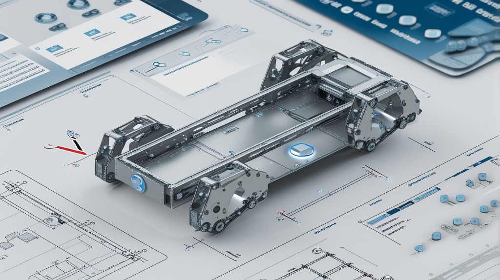
Transform customer BIM or Source File into traceable STEP, 3D and PDF packages, then validate every hole against the source with zero digital tolerance.
 SourceBIM / Source File
EngineTemplate resolved
Validated268 / 268 checks
SourceBIM / Source File
EngineTemplate resolved
Validated268 / 268 checks
One controlled workflow from customer data to manufacturing output
A controlled production chain
No manual CAD template selection. The engine resolves the correct product configuration, generates outputs and verifies the result.
Read BIM or Source File and identify special requirements to process information.
Match the correct product blank and variant using controlled project mappings.
Create digital geometry, hole patterns, positioned weld nuts, browser meshes and drawings.
Compare generated geometry with expected coordinates before manufacturing delivery.
Purpose-built deliverables
Operators receive the exact artifact needed for assembly, machining or quality review, without guessing which file to use.
The manufacturing STEP joins precision hole geometry with positioned subcomponents in one traceable product assembly.
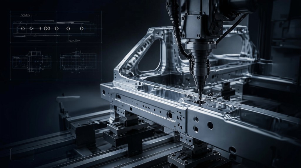
A clean product STEP and dimensional PDF with or without subcomponents geometry.
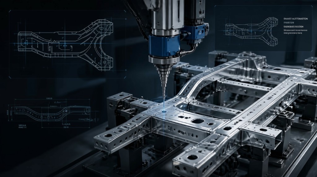
Assembly STEP plus a color-coded PDF reference for production teams.
Geometry you can prove
LogoAQS checks the input before generation, compares expected holes to generated STEP geometry and verifies dimensional PDF output.
Source integrityStructure, numeric data, sides and template resolution
STEP geometryX, Y, Z and diameter against expected hole positions
Drawing outputExpected dimensional content in generated PDF files
Built around the work
A shared product shell connects engineering operations, company management and platform control without fragmenting the workflow.
Throughput, live production and quality signals.
Open ProductionFilter, upload and track every product job.
Open CommercialPlan, monthly job quota and manual invoices.
Open PlatformCompanies, billing and infrastructure health.
OpenIndustrial precision, operational clarity
Sign in to upload BIM or Source File, run validation and download STEP, mesh and PDF packages from one workspace.